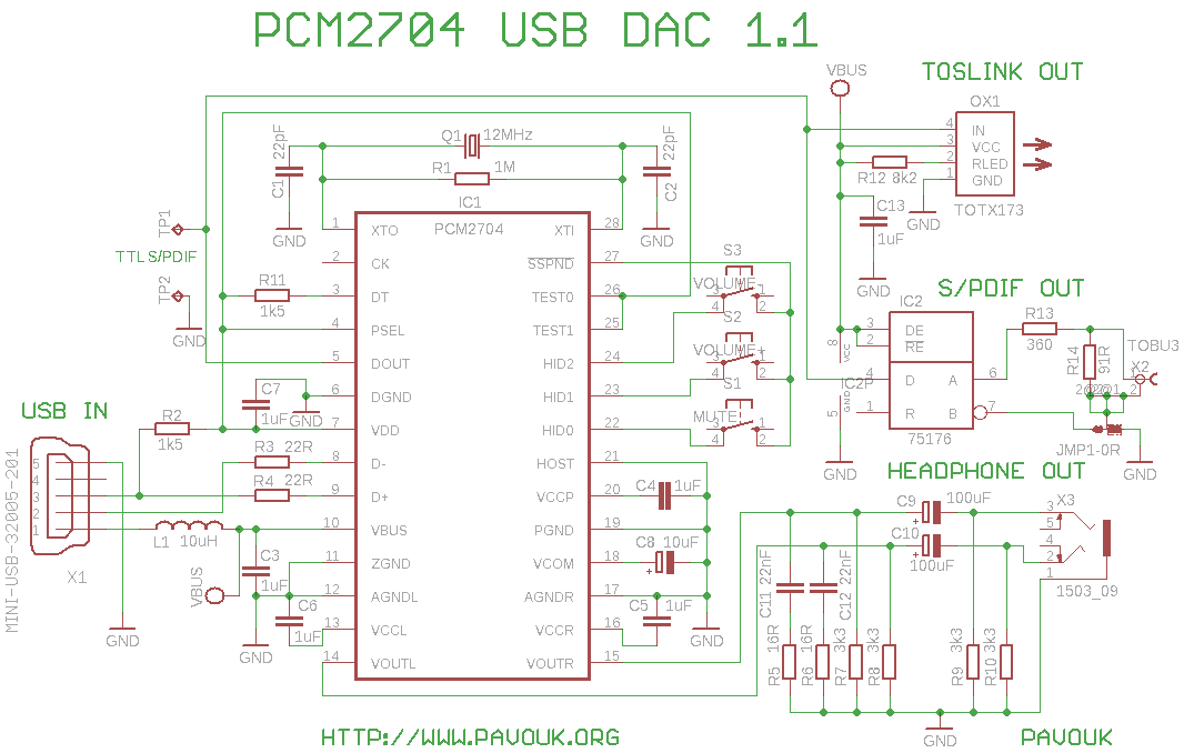
I need for my high quality DAC convertor from USB to S/PDIF. I choose PCM2704 circuit, which sent me TI company like sample. Circuit has analog output for headphones and digital S/PDIF output with electrical and optical(TOSLINK) interface. We can use too 3 HID buttons for setting volume and mute.
Schematics is almost identical to PCM2704 datasheet. Circuit includes these components: DAC, S/PDIF output and HID part with three buttons MUTE, VOL+ and VOL-. For USB input is used standard miniUSB connector. Headphone output uses standard 3.5" stereo jack socket. For signal conversion from TTL level to differential signal is used RS-485 bus transceiver. For optical output is used optical transmitter TOTX173 from Toshiba.
 schematics version 1.1 in Eagle 5 format
First I drill holes for crystal, wires, connectors and buttons. Next I settle intergrated circuit PCM2704, because I need more space for soldering. I put circuit on right place, solder one pin in the corner and next solder all pins on second side with thin tin. Next I solder first side. Effect is, that almost all pins are shorted. Next I must use copper solder wick for draining of tin out. If there are anough colophony that pins automatically unjoin thanks to surface tension. Next I put on the board circuit 75176B, SMD resistors and capacitors. These components I solder that after right position I hold them with nail, small screwdriver or tweezer. One pin I solder with small amount of tin. If the component is on the right place, I solder them on the opposite side and finally on the first side. Next I solder SMD connector, wire junctions and finally all components from a top side. Circuit should work immediately after connection to computer. It is seen as standard USB soundcard. For usual operating systems like Linux or Windows XP are not needed any drivers. It should work too volume settings using buttons.
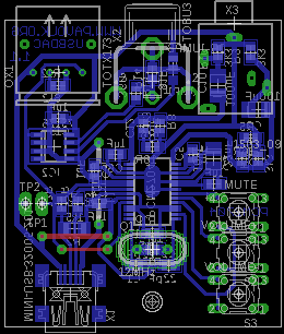
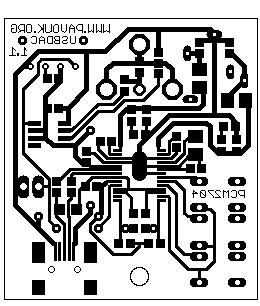
PCB is designed for using only one side with two wire junctions in Eagle 5 application. Almost all components and USB connector are placed from bottom side. From top side are wire junctions, buttons, inductor, crystal and remaining connectors. I tried to separate analog part from digital and right place ground wires to eliminate interferences. PCB is designed for easy creating in amateur conditions.
 version 1.1 in PDF format
version 1.1 in Eagle5 format
version 1.1 in PDF format
version 1.1 in Eagle5 format


| name | value | quantity |
|---|---|---|
| R1 | 1M SMD 0805 | 1x |
| R2 | 1k5 SMD 1206 | 1x |
| R3, R4 | 22R SMD 0805 | 2x |
| R5, R6 | 16R SMD 0805 | 2x |
| R7-R10 | 3k3 SMD 0805 | 4x |
| R11 | 1k5 SMD 0805 | 1x |
| R12 | 8k2 SMD 0805 | 1x |
| R13 | 360R (56R) SMD 0805 | 1 ks |
| R14 | 91R SMD 0805 | 1 ks |
| JMP1 | 0R (56R) SMD 0805 | 1 ks |
| C1, C2 | 22pF SMD0805 ceramic | 2x |
| C3-C7, C13 | 1uF SMD0805 ceramic | 6x |
| C8 | 10uF/25V SMD tantal size B | 1x |
| C9, C10 | 100uF/6.3V SMD tantal size B | 2x |
| C11, C12 | 22nF SMD0805 ceramic | 2x |
| IC1 | PCM2704 SSOP28 | 1x |
| IC2 | 75176B SMD SO-08 | 1x |
| L1 | 10uH | 1x |
| OX1 | TOTX173 | 1x |
| Q1 | 12MHz crystal mini | 1x |
| S1-S3 | microswitch 6x6mm | 3x |
| X1 | miniUSB socket | 1x |
| X2 | cinch socket | 1x |
| X3 | 3.5mm socket EBS35 | 1x |
S/PDIF [Sony/Philips Digital Interface] is designed for transfer of digital audio signal. There exists too professional variant AES3. Both use same protocol with few exceptions. Commercial S/PDIF has for example copy protection. There are also different voltage levels, connectors, impedance and transmission line (balanced/unbalanced). Commercial S/PDIF exists in three variants: Electrical with TTL output (for example CDROM), electrical with voltage level 0.5Vpp on cinch (RCA) connector which use coaxial cable with impedance 75R commonly used on consumer devices and last optical TOSLINK from TOSHIBA. All three transfer methods have identical signal encoding and we can soever convert between them. Transfer speed is taken from sample frequency, number of bits and number of channels. Apart from basic uncompressed PCM encoding is interface today used for transferring of encoded multichannel audio for example Dolby Digital, DTS etc. Advantage of interface is that only one wire is needed for transferring of complete audio signal. It is simultaneously disadvatage, because receiver must reconstruct clock signal from data with PLL and there can rise jitter, which is heared like a small distortion on the output of DAC. For transferring of digital audio within equipment is much better I2S bus.
| Interface name | AES3 | S/PDIF |
|---|---|---|
| Interface | balanced | unbalanced |
| Connector | XLR-3 | cinch (RCA) |
| Impedance | 110 ohmů | 75 ohmů |
| Output voltage | 2-7V p-p | 0.5V p-p |
| Max voltage | 7V p-p | 0.6V p-p |
| Max current | 64mA | 8mA |
| Input sensitivity | 0.2V | 0.2V |
| Cable | STP | coaxial |
| Max distance | 100m | 10m |
I built circuit in two copies and both works on first connection. Analog output has a good sound without interferences and he is better than usual internal soundcards on PC motherboards. Low and middle frequencies are perfect, but highes frequencies are a little blurred. Just it isn't HiFi, but for most people will be quality of sound output sufficient. I built this circuit primary for S/PDIF output which works for me in optical form. Electrical output was not worked, but it may be problem on input of my S/PDIF decoder. This I must more inspect.
There was added S/PDIF chapter. Problems with electric S/PDIF output was solved on receiver side. Schematics and PCB was a little changed. Electrical digital output is now possible create like balanced (AES3) or unbalanced (S/PDIF). When we want S/PDIF, we must connect output through resistor divider R13(360R)/R14(91R) which guarantee right voltage level of output. Output impedance will be about 72R. B output from 75176B we leave unconnected. Shield wire we connect with SMD jumper to the ground. When we want AES3 output with impedance 110R, we must use R13 with value 56R, R14 will be unconnected and on place SMD jumper we will use resistor 56R connecting B output with second output. This makes symmetrical output with impedance about 110R. Connector is usually XLR with three pins with central third pin connected to the ground.
 English
 Česky
Česky