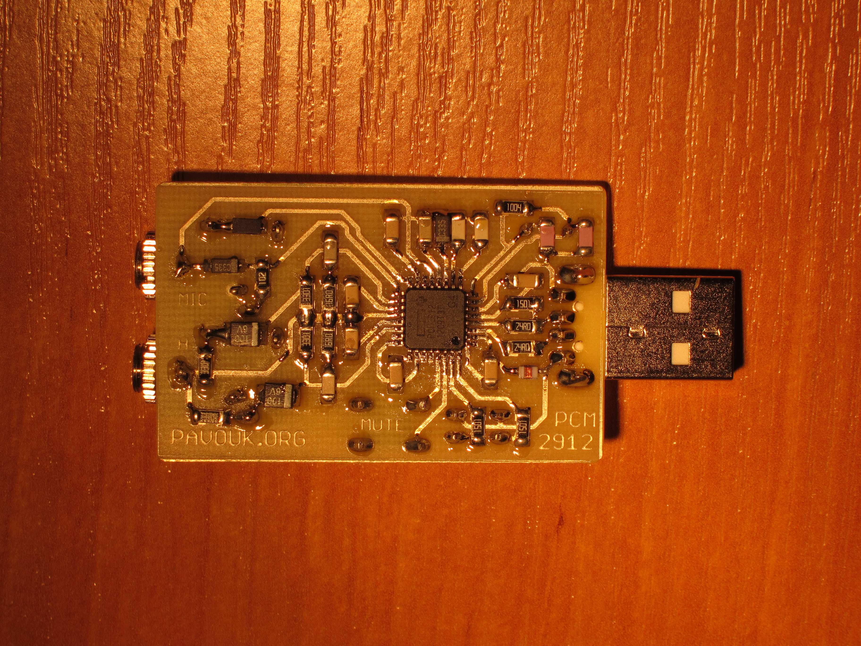
I already built a couple of USB soundcards and converters and I found another interesting circuit PCM2912 which is perfect for building of USB dongle for stereo headphones with mono microphone. This time I designed circuit board like a dongle which is pushed directly to the USB port of computer.
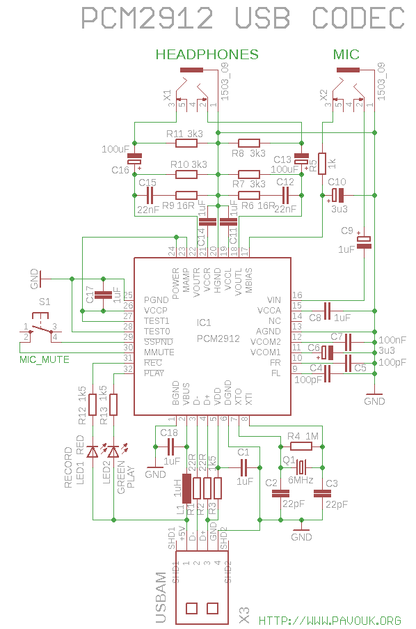
Main part of dongle is PCM2912 circuit from Texas Instruments. On one side of the board is USB type A connector and on the opposite side are two 3.5" connectors for headphones and microphone. Green LED signalize playing and red recording. Button is for mute of microphone. Circuit diagram is practically identical to the schematics in a datasheet.
USB part of chip includes three endpoints. One control endpoint and two audio streaming interfaces for input and output. Control part includes volume control and mute function for input, output and sidetone. Output endpoint allows playing of stereo or mono signal with sample frequency up to 48kHz. Microphone input is always in mono mode.
Except DAC and ADC circuit includes additional 20dB preamplifier on the microphone input which is activated by MAMP pin and amplifier with controlled gain in a range +30dB to -12dB with 1dB step. Between DAC and output is connected controlled attenuator with range 0dB to -76dB with step 1dB. Between microphone input and DAC output is connected one more identical attenuator. It provides sidetone from microphone to headphones. On the MBIAS output is current source for electret microphones. Next is output amplifier for headphones and lowpass filter for suppression of sample frequency and noise. There are also five internal voltage regulators for digital and analog part, both channels of amplifier and PLL. There is already present reset circuit which provides correct reset after power supply connection and clock circuit with PLL which generates master frequency 96MHz from 6MHz crystal for SpAct circuit which guarantee right timing for DACs with respect to sample frequency and low jitter.
There is only minimum of external parts. Except needed decoupling capacitors are there only resistors and capacitors in the output filters and coupling electrolytic capacitors and standard pack of parts around crystal and USB input. There are also two LEDs and one microswitch. In circuit I chose enabled 20dB preamplifier with MAMP pin and Max power 500mA with pin POWER.
Before assembling is a good idea to drill and mill all needed holes for connectors with a small auger. We can already check rest holes for diodes, crystal and microswitch.
We place components on the board from smaller to bigger. We begin with IC1 which is really small. I soldered two opposite pins with a soldering iron. When I was sure, that circuit is on the right place, that I applied fluid flux on all pins which help spilling of tin and I ride across all pins with a soldering iron and tube tin. Few pins was shorted together. Excess tin I easily removed with a solder wick which is perfect for this use. Next I soldered SMD capacitors, inductor and resistors. Next I put the crystal, connectors, LEDs and microswitch from a upper side.
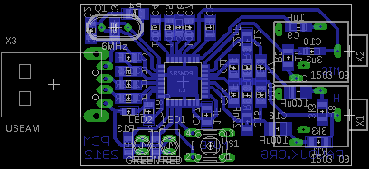
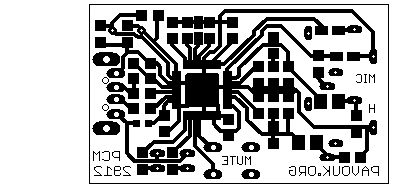
Circuit board is designed single-sided. It allows to create him in amateur conditions. His size is 30x50mm. Almost all SMD components have 1206 size for easy soldering.

Most of the components I bought in a GM Electronic. USB connector in a GES Electronic and integrated circuit PCM2912 at Farnell. Circuit PCM2912 is not recommended for a new constructions because it has hardware bug. But there is produced PCM2912A which is functionally identical and we can use them in this circuit. I found a small difference in a datasheet, that there are missing components R6, R9, C12 and C15 which we don't need to assemble. I used LEDs with a small current (2mA) that I selected resistor values 1k5 instead of 820R from a datasheet. For LEDs with a more current we need to decrease values of R12 and R13 resistors to proper value.
| name | value and type | quantity |
|---|---|---|
| R1-R2 | 22R SMD1206 | 2x |
| R3,R12-R13 | 1k5 SMD1206 | 3x |
| R4 | 1M SMD1206 | 1x |
| R5 | 1k SMD1206 | 1x |
| R6, R9 | 16R SMD1206 | 2x |
| R7-R8, R10-R11 | 3k3 SMD1206 | 4x |
| C1, C8, C11, C14, C17-C18 | 1uF SMD1206 ceramic | 6x |
| C2-C3 | 22pF SMD1206 ceramic | 2x |
| C4-C5 | 100pF SMD1206 ceramic | 2x |
| C12, C15 | 22nF SMD1206 ceramic | 2x |
| C7 | 100nF SMD1206 ceramic | 1x |
| C6, C10 | 3u3/16V electrolytic SMD size A | 2x |
| C9 | 1uF/16V electrolytic SMD size A | 1x |
| C13, C16 | 100uF/6V electrolytic SMD size B | 2x |
| IC1 | PCM2912A or PCM2912 | 1x |
| L1 | 1uH 0.6R SMD0805 | 1x |
| LED1 | LED RED 3mm 2mA | 1x |
| LED2 | LED GREEN 3mm 2mA | 1x |
| Q1 | 6MHz crystal mini | 1x |
| S1 | microswitch 6x6mm middle | 1x |
| X1-X2 | 3.5" socket EBS35 | 2x |
| X3 | USB connector type A to PCB | 1x |
USB dongle works like a charm on the first connection with headphones and microphone. It can be used with a Linux, WindowsXP and newer and Mac OS X too. Drivers are part of operating system that we doesn't need install anything. Dongle is perfectly useful for computers without soundcard or like a second soundcard for VoIP, Skype etc. It can be used in a combination with a software modem for connecting with a radioamateur station. Sound output is pretty good similar to other USB sound chips from Texas Instruments.
-
 English
 Česky
Česky