For testing my DACs I built a simple USB soundcard based on USB codes from Texas Instruments PCM2902. Card has stereo analog input and output, electrical S/PDIF output and electrically isolated input. There is too optical TOSLINK input and output.
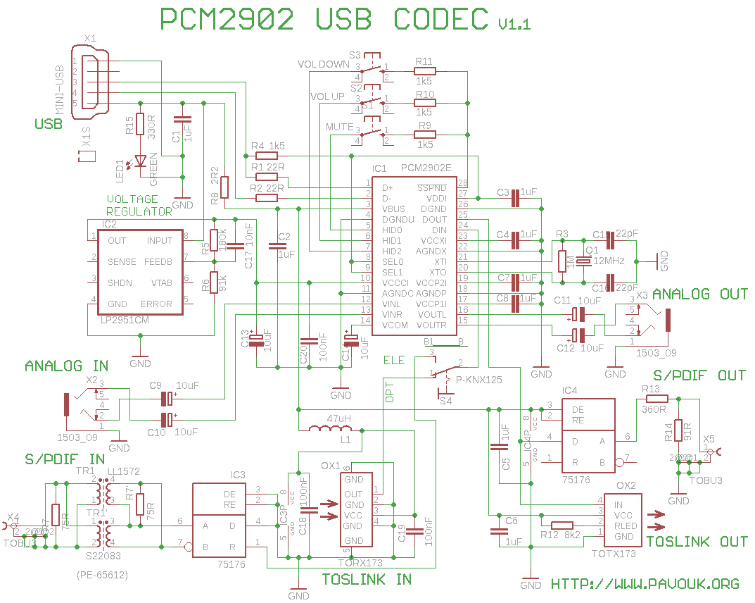
Hearts of the circuit is PCM2902 which is complete USB audio codec. Maximum sample frequency is 48kHz. Integrated circuit includes USB controller for ADC and DAC, HID part for three buttons, output volume control and S/PDIF encoder and decoder.
Circuit is based on recommended circuit from datasheet. For better quality of analog part is used external voltage regulator with IC2. All voltages are blocked with 1uF capacitors. There is optical transmitter TOTX173 and receiver TORX173 connected to IC2. Electrical S/PDIF output is realized with RS422 transmitter IC4. Because for transferring of commercial S/PDIF is used unbalanced coaxial cable with 75R impedance, that I used only one output and with help of voltage divider R13/R14 I reduce output voltage and change output impedance. Usually is specified output voltage maximally to 0.6Vpp. On output of divider is a little greater voltage but I never see troubles with it. S/PDIF receiver includes RS422 transceiver too, but now connected inverse like convertor from RS422 to TTL voltage levels. Input is terminated with 75R resistor R7 which we can place before or after pulse transformer. I had better experience with resistor before transformer. Pulses was looks better on oscilloscope. Digital input is connected over small switch electrical/optical. PCM2902 automatically switch from analog input signal to digital, when it detects presence of S/PDIF signal. Analog output doesn't have additional amplifier, that we can't connect them directly to low impedance headphones. It should be connected to external amplifier.
There is not needed special drivers. I tried full functionality in a Linux, Windows XP and Windows 7. Drivers are included in operating system. There also works HID buttons, volume control and mute.
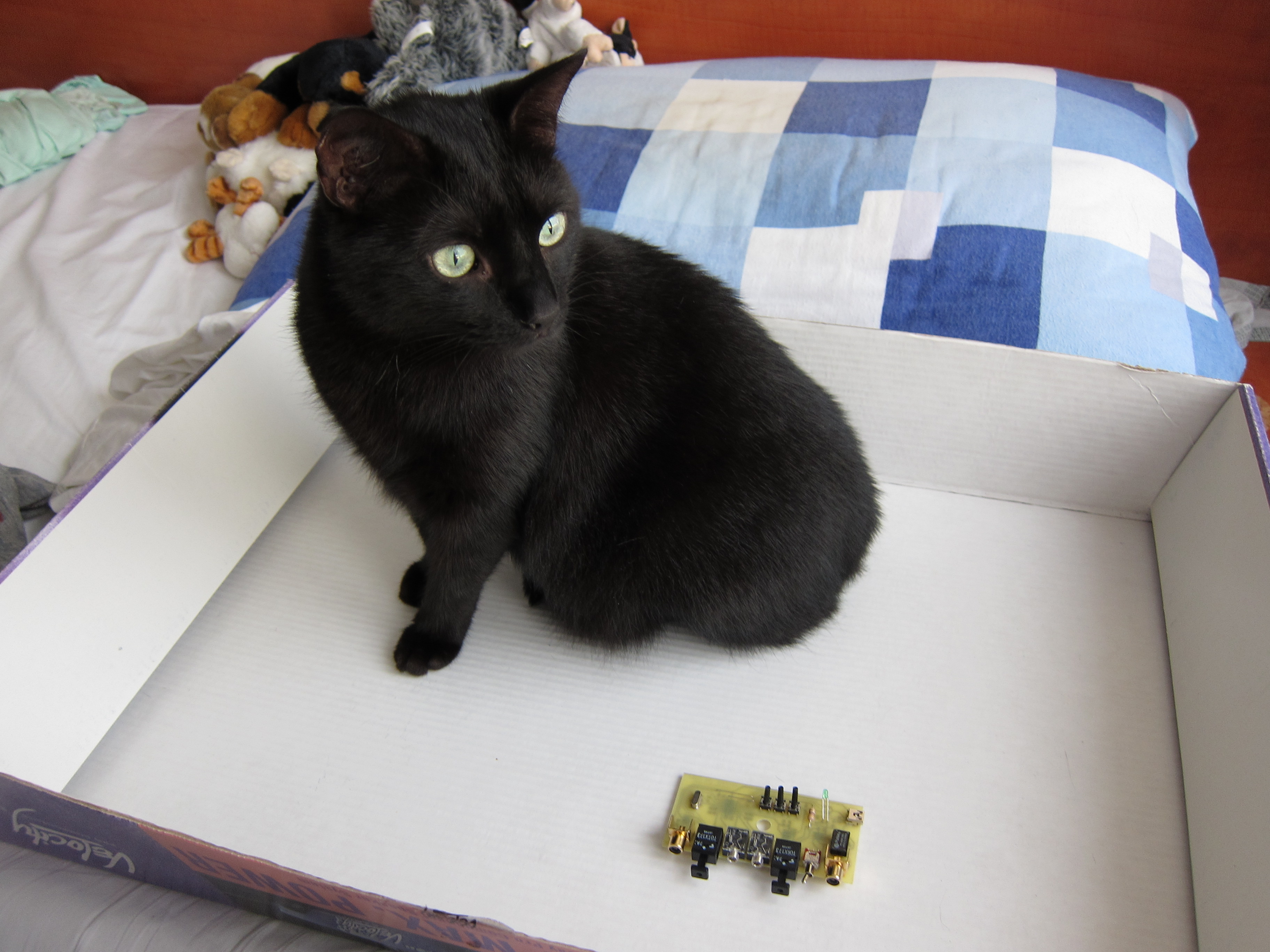
We assemble circuit board from smaller parts to bigger. First I solder IC1 circuit which is really too small. I fix the two pins on a side of circuit with small soldering iron. When I was sure, that circuit is on the right place, that I applied flux on all pins which helps with better diffusion of tin and I soldered first all pins on one side and next on the opposite side. A lot of pins was soldered together. Overflowing tin I easily drain with solder wick. Next I soldered other circuits and I continued with SMD resistors and capacitors. Next I soldered wire junctions and all components from the upper side and last connectors.
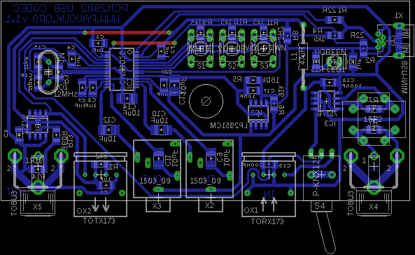
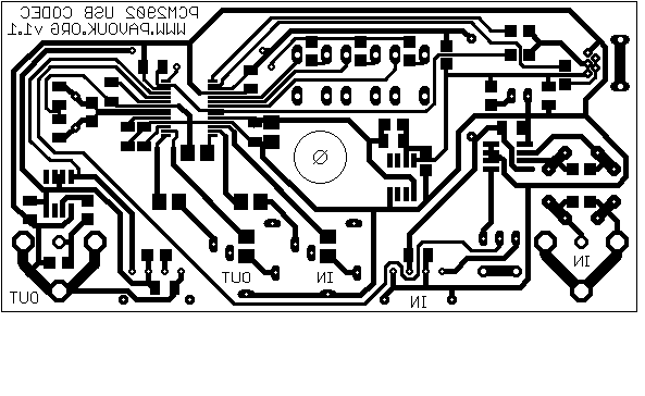
PCB is designed with only one side and two wire junctions. It allow his easy producing in amateur conditions. His dimension fit in plastic box U-KP35B. After assembling I discovered that input switch is reverse connected. Here is corrected PCB version. SMD parts have 1206 size and they are layouted with respect for easy soldering.


Most components I found in a local store GM Electronic, USB connector in GES Electronic and integrated circuit PCM2902 for example in FK Technics. Pulse transformer I bought on EBay, concretely PE-65612. If we doesn't require electrically isolated input, we can replace transformer with two 100nF capacitors.
| name | value and type | quantity |
|---|---|---|
| R1-R2 | 22R SMD1206 | 2x |
| R3 | 1M SMD1206 | 1x |
| R4,R9-R11 | 1k5 SMD1206 | 4x |
| R5 | 180k SMD1206 | 1x |
| R6 | 91k SMD1206 | 1x |
| R7 | 75R SMD1206 | 1x |
| R8 | 2R2 SMD1206 | 1x |
| R12 | 8k2 SMD1206 | 1x |
| R13 | 360R SMD1206 | 1x |
| R14 | 91R SMD1206 | 1x |
| R15 | 330R SMD1206 | 1x |
| C1-C8 | 1uF SMD1206 ceramic | 8x |
| C9-C14 | 10uF/25V elektrolytic SMD size B | 6x |
| C15-C16 | 22pF SMD1206 ceramic | 2x |
| C17 | 10nF SMD1206 ceramic | 1x |
| C18-C20 | 100nF SMD1206 ceramic | 3x |
| IC1 | PCM2902, PCM2902B | 1x |
| IC2 | LP2951CM SMD SO-08 | 1x |
| IC3-IC4 | 75176B SMD SO-08 | 2x |
| L1 | 47uH axial | 1x |
| LED1 | LED green 2mA | 1x |
| OX1 | TORX173 toshiba | 1x |
| OX2 | TOTX173 toshiba | 1x |
| Q1 | 12MHz crystal mini | 1x |
| S1-S3 | microswitch 6x6mm high | 3x |
| S4 | Switch P-KNX125 | 1x |
| TR1 | LL1572, nebo S22083, or PE-65612 | 1x |
| X1 | miniUSB socket USB PCB MBW | 1x |
| X2-X3 | 3.5" socket EBS35 | 2x |
| X4-X5 | cinch socket to PCB TOBU3 | 2x |
| BOX1 | Plastic box U-KP35B 23mm x 54mm x 104mm | 1x |
Introduced circuit works reliable. Measured values approximately match parameters in a datasheet. If we want to use only some inputs or outputs, it is not needed assemble all connectors. Except circuit PCM2902 are expensive optical transceivers and pulse transformer. We can use this circuit like second soundcard or S/PDIF output to STEREO amplifier with digital input. We can use S/PDIF input for connecting other devices with digital output to computer like DAT, miniDISC or CD Player. I measure parameters with RightMark Audio Analyzer (RMAA) and Baudline programs. With RMAA I was much worse results under Windows 7 than under Windows XP. There was some volume control troubles under Win7. I don't know why. Next I continued with testing only under Linux.
-
 English
 Česky
Česky