
My friend ask me for solving problem with dehumidifier which after power loss doesn't start and somebody must go physically to it and push the power-on button and also double push mode button. One of possible solution is to create circuit which after power-on simulates pushing of buttons in requested order.
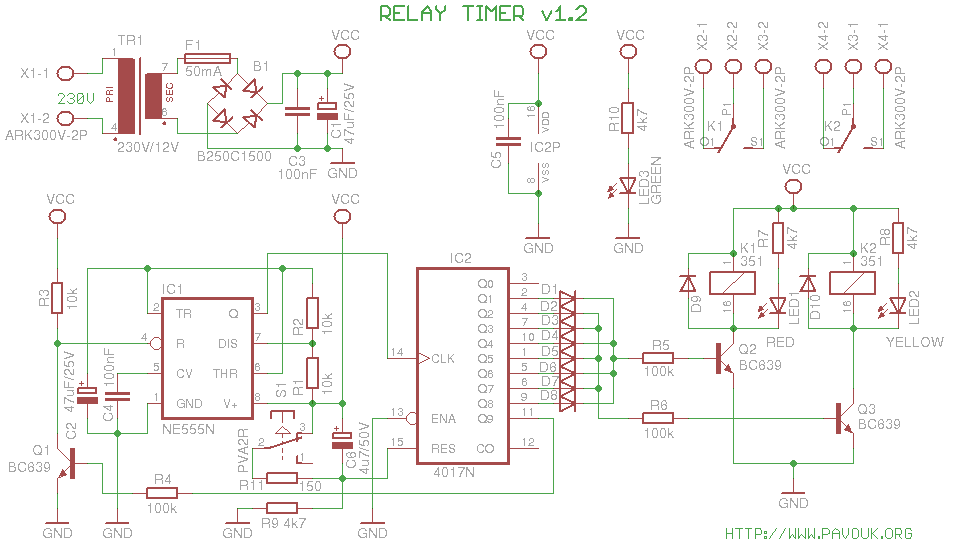
Circuit use well known chip IC1 555 in astable mode. Resistors R1 and R2 and capacitor C2 define generated frequency. It is set around 1Hz. Output from oscillator goes to the clock input of decade counter IC2 4017. On the outputs Q0 to Q9 is step by step logical one for a one clock period. Last output Q9 goes via resistor R4 to the transistor Q1 which block oscillator and counter stop. Next running can be initiated by disconnect of power supply or by pushing the RESET button. Reset also clear the output Q9 and after close of transistor Q1 is oscillator unblocked. I had to add capacitor C6 to the circuit which guarantee correct reset of decade counter after power-on. Resistor R11 in series with button limits discharge current of capacitor C6. Resistors R3 and R9 provides right logical level on the reset signals. Capacitor C4 guarantee better stability of 555 circuit. C5 is decoupling capacitor for 4017. On the outputs Q1 to Q8 is possible connect via diodes power circuits of one, second or both relays. I mounted diodes D1, D3 and D5 which provide one switch-on of relay K1 and two activations of K2. Resistors R5 and R6 limits current to the bases of NPN transistors Q2 and Q3 which switch relay coils. Diodes D9 and D10 protect transistors behind negative peak while relay disconnects. Parallelly to both relays are connected LEDs in series with resistors that we can see which relay is active. On terminal are connected NO and NC contacts of one output of both relays.
Circuit also includes complete power supply. It is used miniature power transformer, fuse, bridge rectifier, filter and decoupling capacitor C1 and C3. Circuit doesn't include voltage regulation. Voltage vary for few volts depend on current consumption and with switched-off relays it has over 20 volts. In this circuit it is not problem. Presence of supply voltage is indicated by LED3. Transformer includes thermal fuse which burns-out after overheat that only one fuse on the secondary side is enough.
When we want that counter will count still around and do not stop that we doesn't mount transistor Q1 and eventually also resistor R4. We can also take out outputs Q1 to Q8 and with transistors switch for example lamps or LEDs and we can have running light. Instead of 8 transistors we can use transistor array ULN2803.
 schematics in PDF
schematics in Eagle 6
schematics in PDF
schematics in Eagle 6
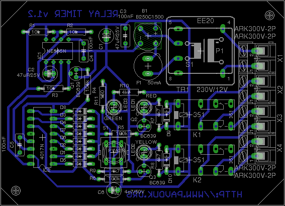
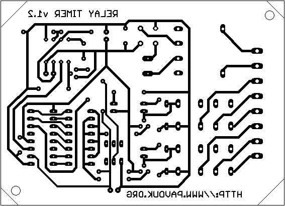
Board is single-sided without any wire junction. it is possible to create them in amateur conditions. His dimensions are designed for placing in to the plastic box U-KM29B. Used cuprextit must be thick maximally 1.5mm and component wires must be cutted very short because on the board tightly fits plastic cover. Connection diode matrix use holes in DIL16 size that if we want sometimes change switch variants that we can put the socket on the board and solder diodes to the another socket which we will change on our requirements. After complete of assembling I found that button is wired in another way than what was clear from datasheet and eagle. I corrected board that button is working. Also difference to the original board are added C6 and R11.


All components are commonly available and it can be easy to buy them in many local stores with components. LEDs are 2mA types. Used relays are not specified for 230V but it is possible to change them for another type with same terminals when coil current will be up to 10-20mA. Microswitch has short button, that i purchased two pieces and one push second.
| name | value and type | quantity |
|---|---|---|
| R1-R3 | 10k | 3x |
| R4-R6 | 100k | 3x |
| R7-R10 | 4k7 | 4x |
| R11 | 150 | 1x |
| C1, C2 | 47uF/25V electrolytic RM2.5 | 2x |
| C3-C5 | 100nF/100V ceramic RM5 | 3x |
| C6 | 4u7/50V electrolytic RM2.5 | 1x |
| IC1 | NE555 DIL8 | 1x |
| IC2 | 4017 DIL16 | 1x |
| B1 | B250C1500 bridge rectifier | 1x |
| D1-D10 | 1N4148 | 10x |
| LED1 | LED 3mm 2mA red | 1x |
| LED2 | LED 3mm 2mA yellow | 1x |
| LED3 | LED 3mm 2mA green | 1x |
| Q1-Q3 | BC639 NPN | 3x |
| TR1 | Transformer EI 20/10 230/12V 0.5VA | 1x |
| K1, K2 | Relay M4-12H | 2x |
| F1 | 50mA PCB fuse | 1x |
| S1 | ZIPPY P1-2S-Z + 2x button | 1x |
| X1-X4 | AK300/2 | 4x |
| KRAB1 | U-KM29B | 1x |
Circuit after fixing of reset works reliable. Construction can be used for other purposes for example running light in arrow form.
 English
 Česky
Česky