Now I tried to build 24 bit DAC without oversampling. I found only one circuit PCM1704 from Texas Instruments which satisfy these requirements. It looks like his production now slowly ending. It is very expensive and because it has only single channel that there are two pieces on the board for stereo. It should be the best what can be builted for playing of 24bit records.
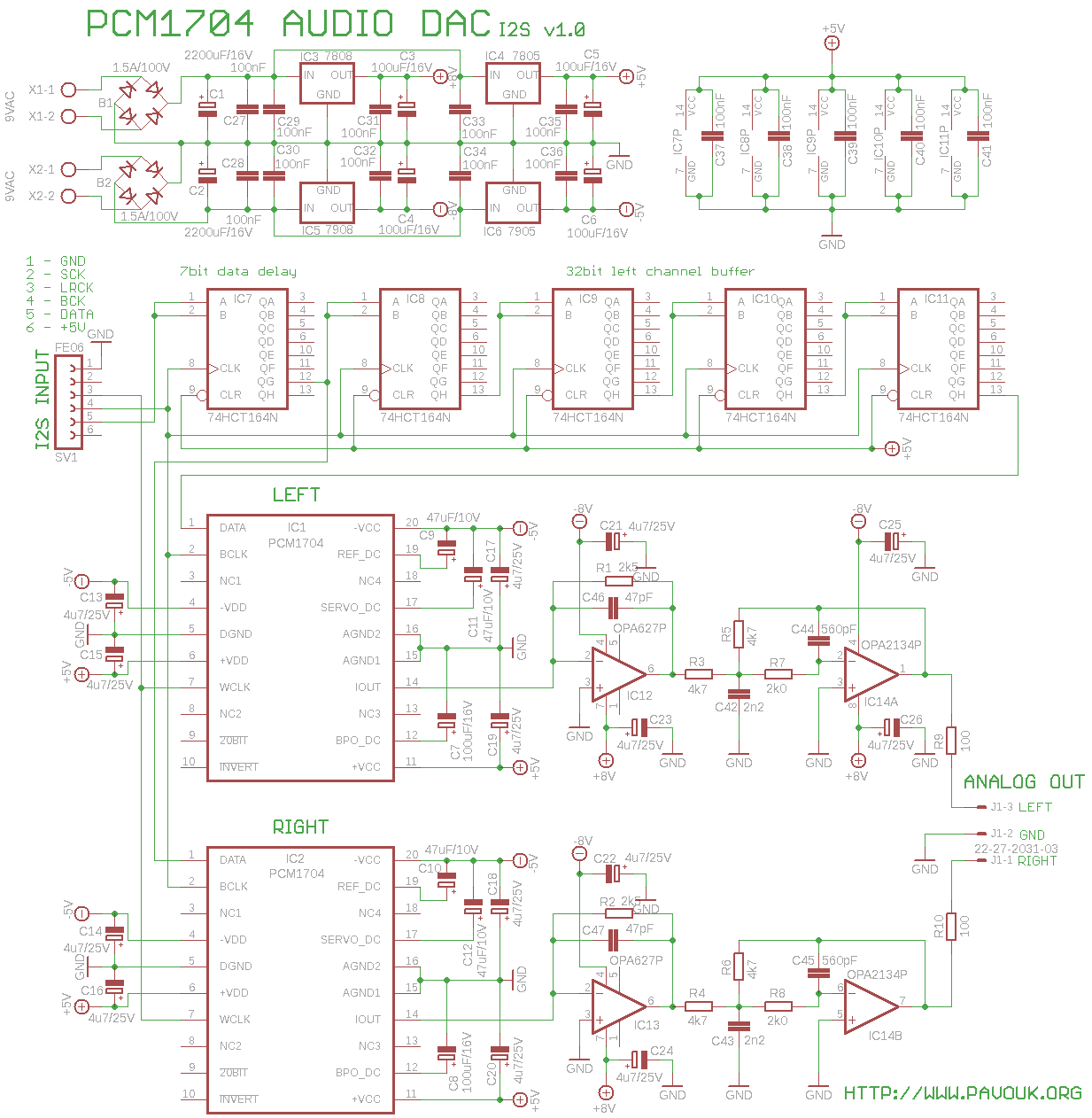
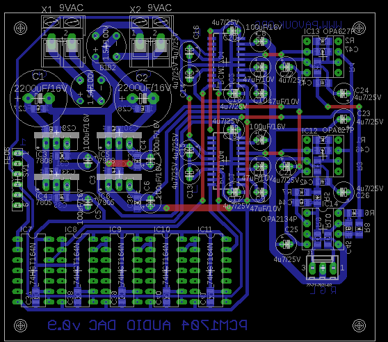
In supply part I used two bridge rectifiers. Theoretically one is enough, but I wanted back compatibility with other boards, where transformer winding for positive branch can be connected also to S/PDIF decoder. Because I want small temperature losts I used transformer with two 9V secondary windings. Because small negative voltage regulators are not available, that I used classic 78XX and 79XX voltage regulators. Capacity of C1 and C2 should be enough thanks to very small current consumption of circuit. Heatsink is not needed. All voltage regulators are properly blocked with 100nF ceramic capacitors and outputs are filtered with C3 to C6 electrolytic capacitors. Every convertor and operational amplifier has on the power line pins additional capacitors recommended in the datasheet.
Convertor accepts data in the 24bit right justified format. I had to connect some logic on the data input. This logic counts with data in the I2S format where data are first delayed for 7 bits with shift-register for correct aligning to 24bit. On the I2S bus are data delayed for 1 bit and left-justified. Thanks to this format we can play data in 16 bit or 24 bit format without any settings change. Next we must buffer 32 bits of data for left channel in four 74HCT164 8 bit shift-registers because we need to play both channels simultaneously and without time-shift. Instead of five pieces of 74HCT164 can be used Xilinx CPLD circuit like in devilsound DAC, but I haven't any experience with Xilinx programming now.
DACs have current output which we must convert to voltage output with I/V convertors. I used recommended circuit with low-noise Difet operational amplifiers OPA627. On their output is connected 2nd order low-pass filter with dual operational amplifier OPA2134 with very low distortion according to recommended circuit in datasheet. On the filter output is signal inverted which is OK in the music, when it is on both channels.
If we want to connect DAC without output filter, that we don't assemble IC14 and capacitors C42 and C43. Resistors R3 to R6 must be replaced with zero resistors. We needn't to assemble R7, R8, C44, C45, C25 and C26. But this is not important, because in the wiring without filter they are not used.
We assemble components on the board from smaller to bigger. We must begin with DACs IC1 and IC2 because later it will not be easy to install them. Next we place all SMD capacitors and resistors. We continue from the top side with integrated circuits IC7 to IC11 and sockets for IC12 to IC14. Next we can assemble all electrolytic capacitors. Beware their polarity! On the end we assemble voltage regulators, rectifiers and all connectors. With careful assembling circuit works on the first power-on.
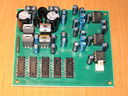
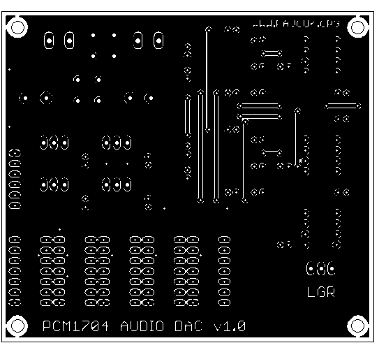
Top side
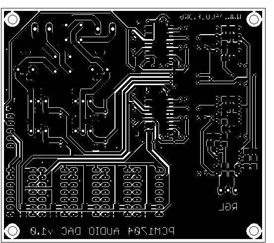
 Bottom side
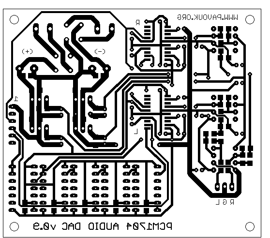
 Version 0.9 with wire junctions
Printed circuit board was this time more complicated with 13 wire junctions. In regard of high price of components I estimated that price of PCB will be minor in all costs and I decided to made professional double-sided board with ground planes and masks. However there is still available single-sided PCB version 0.9 which is in other aspects identical to version 1.0. Routes are still very wide, that worse accuracy class is enough for our PCB. In design I tried to have good separation of analog and digital part and right connection of ground and power lines for minimizing of noise and interference. Data for professional manufacturing of PCB we can generate from Eagle with CAM processor. They are not attached, because every manufacturer has a little different requirements. Usually is generated top and bottom side, board outline and top and bottom mask in GERBER_RS274X format. Drills are generated in EXCELLON format. I ordered board in special prototype service at MEV company which is cheaper for small number of boards. After finish of assembling I cleaned PCB from flux with Isopropyl-alcohol.
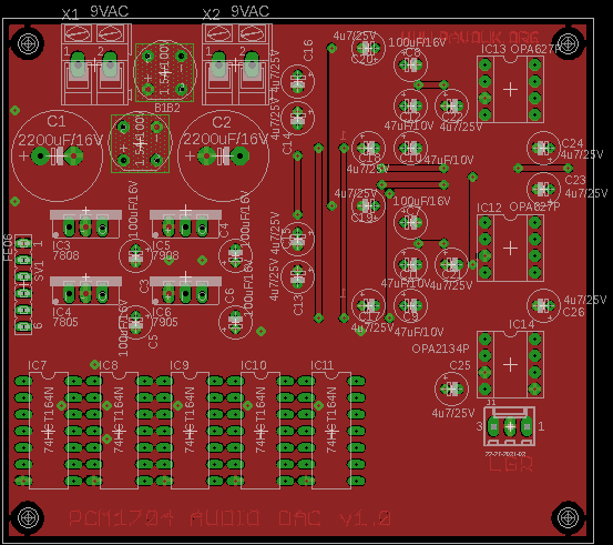
Top side of board version 1.0
 PDF format
Eagle5 format
PDF format
Eagle5 format
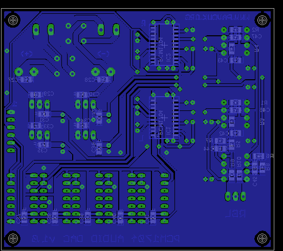
Bottom side of board version 1.0
 PDF format
Eagle5 format
PDF format
Eagle5 format
Board version 0.9
 PDF format
Eagle5 format
PDF format
Eagle5 format


SMD capacitors and resistors have 1206 size that they can be soldered without troubles. DACs and operational amplifiers are expensive and they are not usually available. I bought them at Farnell company. DAC exists in three quality classes. Best is the "K" version, next "J" and last without character. Operational amplifier OPA627 is available in two variants. Class with better accuracy is "BP". On his place we can use theoretically cheap NE5534, but I don't know how much worsen noise and dynamic parameters. Electrolytic capacitors are best with low ESR. I couldn't find them, that I used at least for 105 degree celsius temperature. Other components are easily available. We use transformer with two secondary windings 9 volts preferably with toroid or CI core. Beware on voltage on C1 and C2, because they are only on 16 volts. With 12 volts transformer is on them about 17 volts and they can be destroyed.
| name | value and type | quantity |
|---|---|---|
| B1, B2 | Bridge rectifier 1.5A/100V | 2x |
| C1, C2 | 2200uF/16V low ESR electrolytic RM5 | 2x |
| C3-C8 | 100uF/16V low ESR electrolytic RM2 | 6x |
| C9-C12 | 47uF/16V low ESR electrolytic RM2 | 4x |
| C13-C26 | 4u7/50V low ESR electrolytic RM2 | 14x |
| C27-C41 | 100nF SMD1206 ceramic | 15x |
| C42, C43 | 2n2 SMD1206 ceramic | 2x |
| C44, C45 | 560pF SMD1206 ceramic | 2x |
| C46, C47 | 47pF SMD1206 ceramic | 2x |
| IC1, IC2 | PCM1704U-K(U-J, U) | 2x |
| IC3 | 7808 | 1x |
| IC4 | 7805 | 1x |
| IC5 | 7908 | 1x |
| IC6 | 7905 | 1x |
| IC7-IC11 | 74HCT164(HC, ACT) DIL14 | 5x |
| IC12, IC13 | OPA627BP(AP) | 2x |
| IC14 | OPA2134PA | 1x |
| J1 | Molex 3pin | 1x |
| R1, R2 | 2k5 SMD1206 | 2x |
| R3-R6 | 4k7 SMD1206 | 4x |
| R7, R8 | 2k0 SMD1206 | 2x |
| R9, R10 | 100R SMD1206 | 2x |
| SV1 | Jumper ribbon 6 pins | 1x |
| X1, X2 | Frame terminal AK300/2 | 2x |
| Socket IC12-IC14 | Precise DIL8 socket | 3x |
This construction of DAC with PCM1704 circuits is for the present most expensive from all my DAC constructions but it has a highest quality. I looked on the output signal with oscilloscope and I simple didn't see any interference from digital part to analog. Output sounds for me more dry than with AD1865 based DAC. Reason for this will be probably used low-pass filter. Output of DAC after I/V convertor before filter is absolutely perfect and now best what I see and hear from my constructions. Nothing is added and nothing is lost. In datasheet is written, that maximum sample frequency of PCM1704 is 96kHz with 8x oversampling. I succesfully tests DAC in 24bit/192kHz mode. According to other document from TI is maximum sample frequency 768kHz which is probably true. On the output is not present capacitor. I measured on the one output DC offset 1.6mV and 1.9mV on another, which is probably OK. It is possible to combine DAC with both types of S/PDIF decoders and with USB DAC with I2S output. Unfortunately circuit has now status NRND, that it is not recommended for a new constructions. I am a little sad, that on market wins price over quality.
-
 English
 Česky
Česky