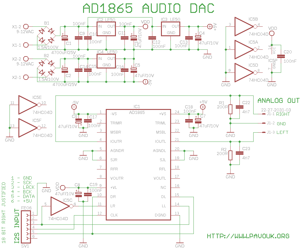
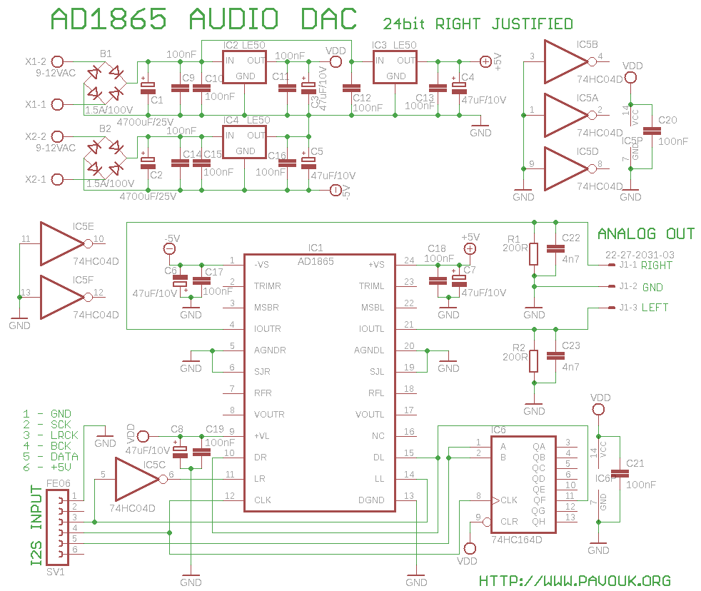
Circuit AD1865 is considered like best 18bit stereo audio DAC ever. It is not recommended for new constructions and probably is not manufactured now. However it is still available on EBay. Circuit has SNR 110dB and THD+N 0.003%. It requires symmetrical voltage +/-5V and it has current and voltage output.
Supplying need two separated windings on power transformer, because I used positive voltage regulator for negative supply branch. After rectifiers B1 and B2 are filter capacitors C1 and C2 and behind them group of block capacitors. I used available low-drop voltage regulators LE50. One is for supplying of digital part and two are for positive and negative analog part of dac. Closely to regulators and integrated circuits are small filter and blocking capacitors.
DAC doesn't have I2S input, which is usual. It has individual data inputs for left and right channel and individual "latch" inputs which rewrites data from internal register to DAC. Circuit is in two variants, because DAC has 18bit data format input and some SPDIF decoders knows only 16 or 24 right justified output. For connecting with DIR9001 I have to connect additional shift register IC6 which delays data for 6 bits. With this modification DAC works with 24bit right justified format. SPDIF decoder CS8414 knows 18 bit output, but I didn't have them.
Data are in sequence shifted in to the internal shift register of dac first for one channel and after switch of LRCK for second channel. For changing of channels we must latch signal negate for right channel. This connection introduce effect, that left and right channels are not played simultaneously and they are time shifted. It usually doesn't matter, because it is not hearable. It can be theoretically hearable on headphones. it can be solved with 32 bit shift register which delays data for one channel, registers in a dac will be fulled simultaneously and rewriting to dacs will be at one time. Unconnected inputs of IC5 must be connected to ground, because there can be parasitic oscillations.
For analog output I used current output and passive I/V converter with resistors R1 and R2. This output should be highest quality specially with high quality resistors but it must not be very loaded. It should be connected to preamplifier with short cable.
 schematics of 18 bit version in Eagle 5 format
 schematics of 24 bit version in Eagle 5 format
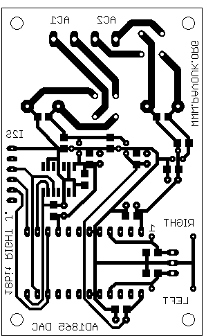
We assemble PCB from smaller parts to bigger. We begins with SMD parts and next with parts with wires. First I installed IC5, eventually IC6 and after them SMD capacitors. Circuits we can solder with small soldering iron and small 0.5mm tube tin. In case of emergency we can use transformer soldering iron and bigger tin. When some of pads will be connected together, we can exhaust overflowing tin with solder wick. Next I installed resistors and small capacitors from top side and next voltage regulators, connectors, dac and big capacitors.
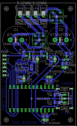
PCB is single sided without wire junctions. It help as to make them in amateur conditions. SMD parts are from a bottom side and parts with wires and connectors are from a top side. Supply wires are designed with accent on right ground wiring and junction of analog and digital ground in a one point. Block capacitors are very close to circuits. PCB has four assembling holes for mounting with screws.
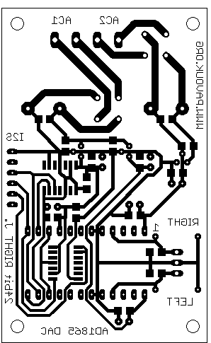
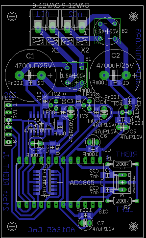
Board is almost identical to 18bit version. In addition includes circuit IC6 and blocking capacitor C21. This board is suitable for connecting with DIR9001 SPDIF decoder.


SMD capacitor have 1206 size which help with soldering. Integrated circuits in SO14 package we can solder too. Except AD1865 circuits, which I bought on EBay are all components commonly available.
| name | value and type | quantity |
|---|---|---|
| R1, R2 | 200R 0.5W | 2x |
| C1, C2 | 4700uF/25V elektrolytic | 2x |
| C3-C8 | 47uF/10V low ESR elektrolytic RM2.5 | 6x |
| C9-C20 | 100nF SMD1206 ceramic | 12x |
| C22, C23 | 4n7 SMD1206 ceramic | 2x |
| IC1 | AD1865 | 1x |
| IC2-IC4 | LE50 | 3x |
| IC5 | 74HC04 SMD SO14 | 1x |
| J1 | Molex 3pin | 1x |
| B1, B2 | Bridge rectifier 1.5A/100V | 2x |
| SV1 | Jumper ribbon 6 pins | 1x |
| X1, X2 | Frame terminal AK300/2 | 2x |
| Additional parts for 24bit version | ||
| C21 | 100nF SMD1206 ceramic | 1x |
| IC6 | 74HC164 SMD SO14 | 1x |
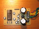
First I built 18bit version. When I had only noise from output that I got across that with 24 bits right justified data will be 6 bits shifted out from a shift register of dac and they must be delayed. I easily solve these troubles with 74HC164 circuit. Analog output sounds great and looks very nice on oscilloscope. I must only built DAC in a box and finish preamplifier.
-
 English
 Česky
Česky