
Before many years I found construction of almost perfect headphone amplifier in pure class A. Before some time I also built it and make it alive but don't install it in the chassis. Now I found them and I will try to describe my experience with it. Amplifier was designed by Kevin Gilmore and his construction was published in this article: A Pure Class A Dynamic Headphone Amplifier. Construction exists on the internet in many variants with more or less changes. I designed PCB for one channel in original variant and next modified version known under name Dynalo. Next I designed circuit and PCB of simple power supply.
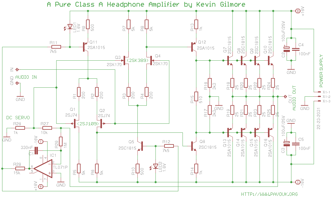
Input stage is created by transistors Q1-Q4 and is fully symmetric and creates bias for second stage and guarantee that output stage will be always in class A. Individual transistor idle current is 1mA. For input stage are used dual low-noise JFETs specially designed for audio but today are not manufactured and it is almost impossible to buy them. Voltage gain of the input stage is 50. LED1, Q11 and LED2, Q5 are accurate current source for input transistors.
Driver stage was made up from transistors Q12 and Q6 and have voltage gain 0.5 and idle current 4.3mA. It is constructed like voltage amplifier.
Output stage is a symmetric quartet of parallelly connected emitter followers Q7-Q10 and Q13-Q16. It has gain 0.9 and idle current about 15mA per transistor with power supply +/- 16V. It makes transistors relatively hot but not too much for need of heatsink.
Thanks to the symmetrical design amplifier doesn't need on the input and output coupling capacitor which can decrease quality of sound. While we are matching components that there can be still present on the output small DC voltage. In circuit is used DC servo which can shift output voltage to the zero with a small change of current of input transistors. Servo is integrator. Thanks to the relatively huge capacity of C1 and resistor R29 is frequency of filter about 0.05Hz. With a good operational amplifier is his noise insignificant. Operational amplifier measure DC voltage on the output, integrate it and apply it to the middle point of LEDs. In consideration to the current change on the LED is his voltage changed only a little maximally about 3-4% which is enough for servo to work. Of course we must have transistors matched because control range of servo is only about 10%.
Small DC voltage is not a problem for high-impedance headphones. But if we will have DC voltage on the low-impedance headphones like Grados for a long time that we can change their sound or destroy them.
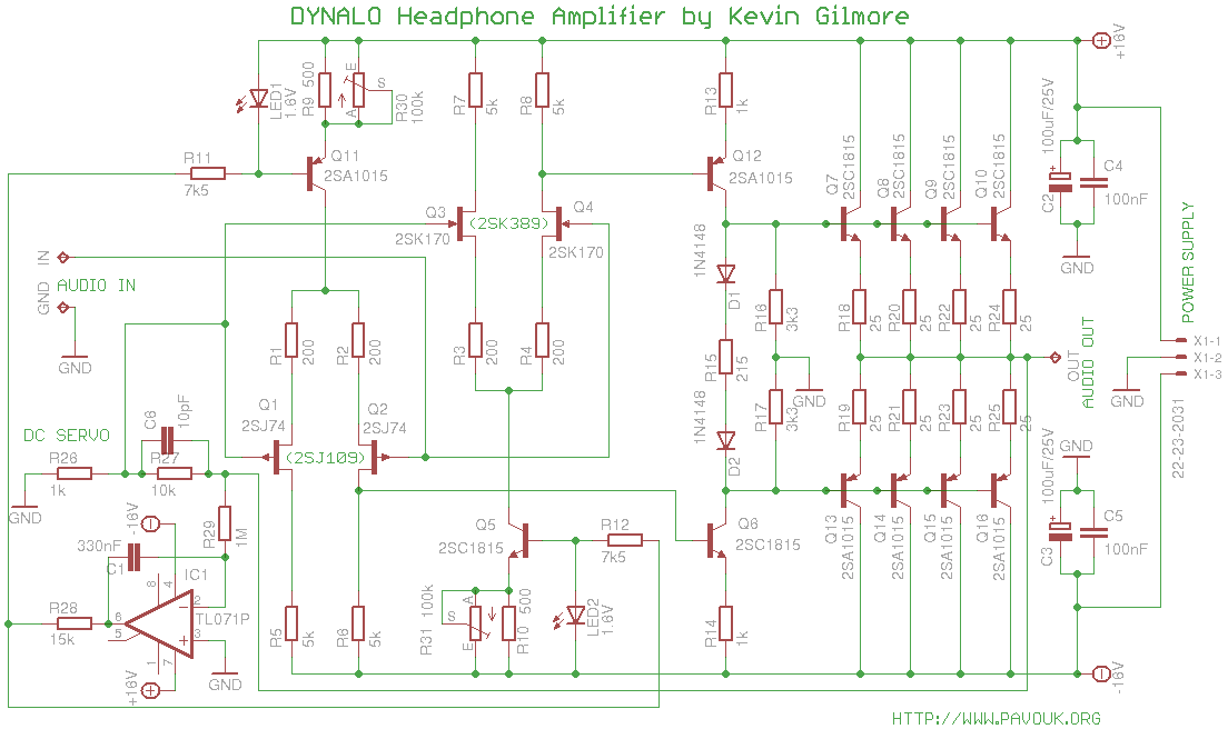
Difference between Dynalo and original circuit is adding of trimmers R30 and R31 for fine-tuning of idle current. There are also added diodes D1 and D2 for thermal compensation of idle current of output transistors. With diodes we must use other value of R15. There was also added small capacitor C6 for feedback compensation.
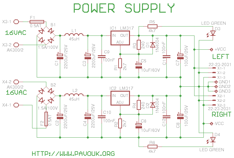
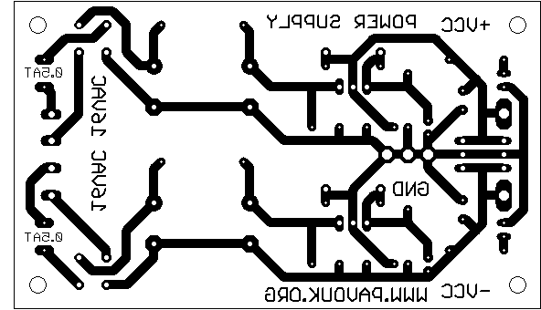
Power supply requires transformer with two secondary windings 15-16V. I will describe only positive branch because negative is identical. Voltage from a transformer goes to the bridge rectifier B1 and next to the capacitor C1. After filtering coil L1 is filtering capacitor C3. Next is voltage regulator LM317 in typical connection. Output voltage is adjusted by combination of R1 and R3 to the value about 15 volts. Capacitor C9 is needed for regulator stability and C5 improve noise parameters. D1 is protection diode for discharge of C5. Next is decoupling capacitor C11 and small filtering capacitor C7. On the output voltage is connected LED D3 via R5 which indicates presence of voltage.
We begin with assembling of all resistors. Circuit is critical for accuracy of parts specially around input JFET transistor stage that we will use precise resistors. We can buy them more and next select which are more accurate. Next we continue with assembling of Q5 and Q11 which must have almost identical H21e. Next we assemble LED1 and LED2 which could have identical voltage if it is possible. We can buy them more and select from them. Next we assemble other bipolar transistors Q6 to Q10 and Q12 to Q16. Again we will try to select transistors with similar parameters. If we are building Dynalo version that we assemble diodes D1 and D2 which could be ideally thermally connected with output transistors via small heatsink. We also assemble trimmers R30 and R31. First we must turn them to the position with maximal resistance! Second group of matched parts we will use for second channel board. Next we assemble JFET transistors. Ideally doubled types 2SJ109BL and 2SK389BL. I found only 2SJ74BL and 2SK170BL. BS marks Idss classification 6 to 12mA. We must give big attention on the transistor orientation because PCB was primarily designed for dual transistors. Photography can help. Next we assemble capacitors but operational amplifier we don't assemble. We will wait with them on the first power-up and adjustment. Same procedure we will applicate on the second board.
This board we will assemble from small components to bigger. Specially we will select resistors R1, R2 and R3, R4 for precise adjustment of output voltages. Ideally power supply could be perfectly symmetric. On the place of L1 and L2 we can also use 2W resistor with a small resistance about 1 ohm. After assembling we will connect power supply board to the transformer and if everything is correct that LEDs D3 and D4 will light and on the output will be voltage about +/- 15V. I measured 15.33V.
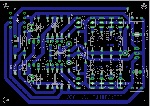
Printed circuit boards are single-sided with wide paths and it is possible to create them in amateur conditions. I ordered them at small local company Kohout Spoj.
If you checked that power supply give a right voltage, connect amplifier input to the ground or turn connected potentiometer to the left position and connect one channel to the power supply.
Now check with multimeter a few points that we will see if everything works right. On the R9 and R10 must be voltage around 1V which means current 2mA from a current source. I measured 1.048 to 1.05 volts. If the voltage is smaller than 0.85V or bigger than 1.15V that something is wrong. Maybe there can be used LED with other voltage than 1.6V.
On the resistor R15 we could measure slightly over 2 volts which means idle current 4mA of voltage amplifier. I measured 2.035V. With Dynalo variant we will have on the resistor R15 with value 215 ohms voltage about 0.86V.
On the resistors R18 to R25 we could measure voltage about 0.37V which means idle current 15mA per transistor in output stage. If the voltage is smaller than 0.32V or bigger than 0.44V that something is wrong. I measured after warm-up voltage about 0.39V. Dynalo version could better stabilise idle current in output transistors with thermal feedback via diodes D1 and D2. Power loss is about 240mW on every output transistor.
If everything looks fine that we can now measure DC voltage on the output. If we precisely matched parts that we could measure from -50mV to +50mV on the output of amplifier. If we have Dynalo version that we will try to reduce DC offset with trimmers R30 and R31. They could be turned to the position with maximum resistance. We begin to turn with one of them and when offset increasing that we turn them back and we begin turn with second until offset will be under 5mV. If we don't like trimmers that we can measure resistance of combination R9 with R30 and R10 with R31 and replace them with fixed resitors with measured value.
When we succesfully minimised DC voltage offset on the outputs that we can now solder operational amplifier IC1 which works like a DC Servo. If servo works correctly it could be visible on the output of amplifier. Offset slowly decreasing and moving around zero maximally +/-2mV and ideally +/-1mV. It is really important that DC offset will be minimised before servo assembling because servo has very small range of regulation and with too big offset will not work. At Dynalo version we can after cold start fastly fine-tune offset with trimmer.
It is the best to build-in amplifier in to the metal chassis. On the photos
is viewed installation in to the Hammond aluminium box. It is important
to have supply transformer and wires far from audio input wires. It is a good idea
to use toroid transformer which has smaller magnetic field radiation.
Also we must beware on ground loops. Ground from both boards and from the
output connector goes to the central point on the power supply board.
Ground from a input connectors goes to the potentiometer and next
directly on the amplifier boards. It is a good idea to use shielded wire
for input signal. Alternatively it is possible to connect ground from the input
to the central ground point and not to connect it to the boards.
We will place potentiometer close to the inputs and for the connection with knob
on the front panel we will use extension stick. On the voltage regulators we will
screw small heatsinks. If we have bigger chassis that we can use power filter
and fuse on the input from a power cord. It is evident how chassis is wired
from a picture.

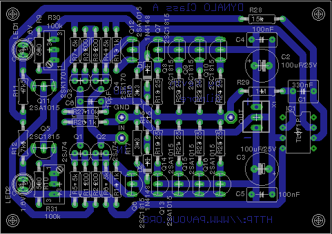
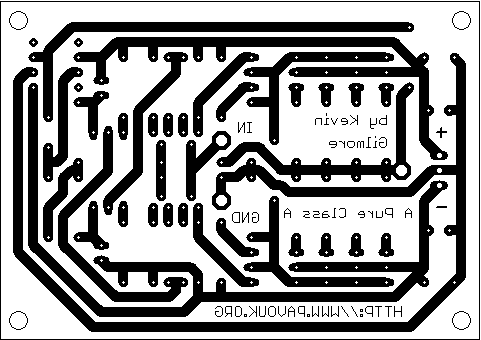
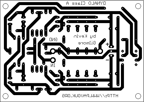
Amplifier board
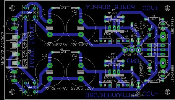
 Power supply board
 Complete amplifier foto © Martin Saidl
 Opened amplifier foto © Martin Saidl
 Front side view foto © Martin Saidl

It is still harder to find JFET transistors. Some shops offer transistor matching service. It is a good idea to buy at least 1% resistors. We can buy bigger amount of other transistors because they are cheap. Matching will be much easier. Also we can buy more LEDs. We select really only RED LEDs of same type with 1.6V voltage. For potentiometer we can use for example 10k logarithmic type RK27 series from ALPS. We must never turn-on amplifier without potentiometer or resistor on the input. Headphones can be destroyed. Transformer is best toroidal type or flat type with CI core. If we use transformer in external box or we will use bigger chassis with more space that we can use also cheaper transformer with EI core. Other components are easily available in a local store.
| name | value and type | quantity for two boards |
|---|---|---|
| R1-R4 | 200R 1% | 8x |
| R5-R8 | 5k 1% | 8x |
| R9, R10 | 500R 1% | 4x |
| R11, R12 | 7k5 1% | 4x |
| R13, R14, R26 | 1k 1% | 6x |
| R15 | 215R 1% | 2x |
| R16, R17 | 3k3 1% | 4x |
| R18-R25 | 25R 1% | 16x |
| R27 | 10k 1% | 2x |
| R28 | 15k 1% | 2x |
| R29 | 1M 1% | 2x |
| R30, R31 | 100k trimmer type 64W (only DYNALO) | 4x |
| C1 | 330nF/63V foil RM5 | 2x |
| C2, C3 | 100uF/25V electrolytic low ESR 105°C RM3.5 | 4x |
| C4, C5 | 100nF/63V foil RM5 | 4x |
| C6 | 10pF ceramic RM5 | 2x |
| D1, D2 | 1N4148 | 4x |
| IC1 | TL071P DIL8 | 2x |
| LED1, LED2 | RED LED 1.6V 5mm | 4x |
| Q1, Q2 | 2x 2SJ74BL (1x 2SJ109BL) | 4x (2x) |
| Q3, Q4 | 2x 2SK170BL (1x 2SK389BL) | 4x (2x) |
| Q5-Q10 | 2SC1815 | 12x |
| Q11-Q16 | 2SA1015 | 12x |
| X1 | Molex 3pin | 2x |
| name | value and type | quantity |
|---|---|---|
| B1, B2 | Bridge rectifier 1.5A/100V | 2x |
| C1-C4 | 2200uF/25V electrolytic low ESR 105°C RM7.5 | 4x |
| C5, C6 | 10uF/63V electrolytic low ESR 105°C RM2.5 | 2x |
| C7, C8 | 100uF/25V electrolytic low ESR 105°C RM3.5 | 2x |
| C9-C12 | 100nF/63V foil RM5 | 4x |
| D1, D2 | 1N4004 | 2x |
| D3, D4 | LED green 2mA | 2x |
| F1, F2 | Radial PCB fuse T500mA | 2x |
| IC1, IC2 | LM317 TO220 package + small heatsink | 2x |
| L1, L2 | 45uH axial 500mA | 2x |
| R1, R2 | 2k7 1% | 2x |
| R3, R4 | 240 1% | 2x |
| R5, R6 | 4k7 | 2x |
| X1, X2 | molex 3pin | 2x |
| X3, X4 | Terminal AK300/2 | 2x |
| TR1 | Transformer 230V/2x15V 2x8VA | 1x |
This Class A headphone amplifier has excellent sound and sufficient output power for almost all headphones. Construction is relatively simple but very hard to component matching and adjusting. Biggest problem is availability of JFET transistors. Amplifier was succesfully built in many pieces and variants.
-
 English
 Česky
Česky