
We can build high quality integrated headphone amplifier from two circuits. One is TPA6120A2 with two channels and second is LME49600 which has only one channel. With first I already built amplifier that now I used two pieces of LME49600. We can use amplifier simultaneously for headphones and like preamplifier for power amplifier.
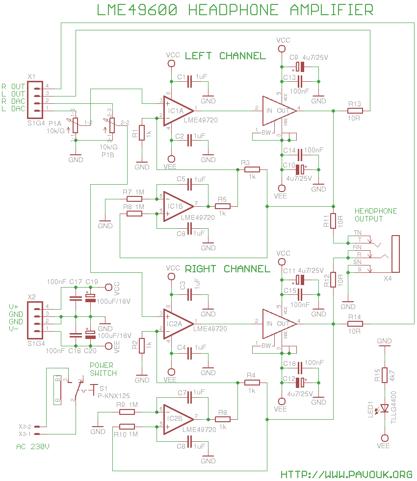
Circuit is same like in a recommended circuit in a datasheet. LME49600 is a buffer with output current up to 250mA. It is connected in the feedback path of operational amplifier LME49720. This operational amplifier is specially designed for HiFi audio circuits. His second half is used in DC servo circuit. Whole circuit is designed that that on the input and output are not present DC block capacitors which can have negative impact on the sound.
I will describe circuit only for left channel. Second channel is same. Input signal goes via potentiometer P1A to the non-inverting input of operational amplifier IC1A. His output is connected to the input of buffer IC3. Amplified signal goes via R11 on the front headphone output and via R13 on the rear output for connecting of power amplifier. Both resistors are attended for better stability when capacitive load is connected. From output of IC3 goes feedback via R3 to the inverting input of operational amplifier and together with R1 set gain to 2. On inverting input is also connected output from DC servo via R5 which looks like connected to the ground that parallelly to the R1. It cause that complete gain is 3. When DAC generates 0dB signal that I measured voltage about 5.6Vpp on the input of amplifier and with potentiometer on the maximum was 16.5Vpp on the output. Measured parameters correspond to complete gain 3x. Output buffer is unity-gain.
IC1B is connected like integrator. Combination R7 and C5 set upper border frequency to 0.16Hz. This is sufficiently low that DC servo doesn't influence sound on the low frequencies. DC servo trying to compensate possible DC voltage on the output from thermal reasons or parts toleration and keep them around zero. On the left output I measured DC offset 10.1mV and 4.3mV on the right channel.
Board has on the power input decoupling capacitors C17 and C18 and filter capacitors C19 and C20. From a stability reason IC1 has decoupling capacitors C1 and C2 close to the chip. Similar there are decoupling capacitors C9, C10 and C13, C14 close to the output buffer. On the board is also power switch and LED indicating presence of supply voltage.
First I assembled buffers IC3 and IC4. I slightly tinned area on PCB and bottom side of parts. I worried if parts will not be oxidised but tin connects perfectly. Next I soldered chips to the PCB with outer pins 1 and 5. Now I loaded chip with a huge piece of steel and I begin to run with soldering iron at the edge of part together with tin. Chip was heated and suck tin under them. After few seconds noticeable dropped down to the board. After cool down I soldered rest pins. It is a good idea to use enough of flux while soldering. Probably best is gel flux but colophony is also usable. I used high quality tin with lead because it makes much better joints that lead-free tin. Next I assembled SMD resistors and capacitors. Beware to polarity of electrolytic capacitors. Next I added operational amplifiers, connectors, switch and potentiometer. For safe I added under potentiometer a piece of isolation tape because near to the pins are metallic pieces which can theoretically fray isolation paint on the PCB. We must precisely mount connectors between boards that they will be soldered in right angle. Next they will go easily to the sockets of the neighbour board. It is also needed to set right position of the LED to precise fit to the hole in the front panel.
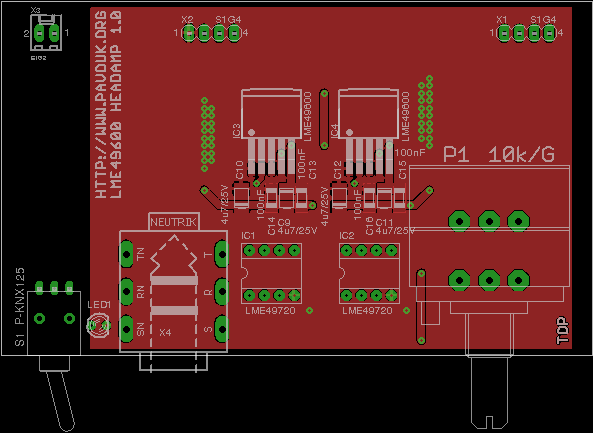
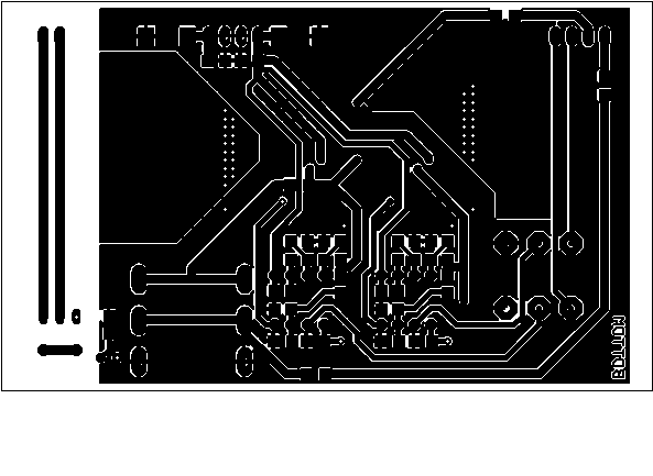
Printed circuit board is doublesided. Huge part of surface is used for cooling of buffers which is enough for them. Connections are designed with accent on the star supply lines and good wiring of ground. Components are placed far from power supply board to eliminate interference. Ideal thickness of board is 2mm to precise inserting to the slot in a Hammond chassis. I ordered PCB manufacturing at Seeed Studio. Required Gerber and Excellon files is possible to generate in a Free version of Eagle from a data which are available here.
View to the fully populated opened box.
 Top side view.
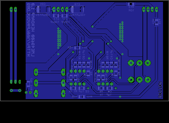
Bottom side view.
Top side view.
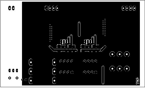
Bottom side view.
 Front panel view.

We can purchase parts for example at Farnell company. I bought potentiometer at SOS Electronic company. Smaller SMD components have size 1206 for easy soldering in amateur conditions.
| name | value and type | quantity |
|---|---|---|
| C1-C8 | 1uF SMD1206 ceramic | 8x |
| C9-C12 | 4u7/25V SMD tantal size B | 4x |
| C13-C18 | 100nF SMD1206 ceramic | 6x |
| C19, C20 | 100uF/25V SMD tantal size D | 2x |
| IC1, IC2 | LME49720 DIL8 | 2x |
| IC3, IC4 | LME49600 TO-263 | 2x |
| LED1 | Green 2mm cylinder type | 1x |
| P1 | 10k/G dual potentiometer ALPS-RK27 | 1x |
| R1-R6 | 1k SMD1206 | 6x |
| R7-R10 | 1M SMD1206 | 4x |
| R11-R14 | 10R SMD1206 | 4x |
| R15 | 4k7 SMD1206 | 1x |
| S1 | P-KNX125 | 1x |
| X1, X2 | Jumper ribbon 4 pins S1G4 90° | 2x |
| X3 | Jumper ribbon 2 pins S1G2 90° | 1x |
| X4 | Connector Neutrik NMJ6HCD2 | 1x |
Amplifier sounds very good. Without troubles can drive high impedance headphones. It is very stable with all kinds of load. His parameters are perfect but with maximum turn of potentiometer we can hear a little noise with low impedance headphones. I must say that with this power headphones will be probably damaged. Very good loudness is already from 1/4 of potentiometer track with 32ohm headphones. Amplifier is linear for a whole audio spectrum. Thanks to oversized power supply is not problem with low frequencies. What I doesn't like is relatively big punch to headphones while power on or off. Maybe I will try to change voltage regulator because supply is not perfectly symmetric. I had worries about temperature of chips but they are after long time only a little warm.
-
 English
 Česky
Česky